
Marine loading arms, also known as MLAs or MLA, are articulated rigid-pipe systems used to transfer liquid or gaseous products between a marine terminal and a vessel.
They are used at oil, chemical, petrochemical and gas terminals for the loading and unloading of crude oil, fuels, chemicals, LPG, LNG and other industrial fluids.
One of the main differences between a flexible hose connection and a marine loading arm is that the latter consists of rigid piping sections connected by swivel joints. This configuration allows the arm to follow vessel movements relative to the jetty while maintaining a safe connection to the vessel manifold.
The selection and design of a marine loading arm depend on much more than pipe diameter. The product to be transferred, flow rate, vessel characteristics, environmental conditions, jetty geometry, operating envelope and required safety systems are among the parameters that must be considered.
To learn more about our commercial solutions, visit our Marine loading arms.
During transfer operations, the vessel is continuously subject to movement caused by tidal variations, waves, wind, motion within the mooring system and changes in draft as cargo is loaded or unloaded.
The loading arm must be able to follow these vessel movements without transmitting excessive loads to the vessel manifold or to the loading arm structure itself.
For this purpose, the arm incorporates several articulated sections equipped with swivel joints, providing the degrees of freedom required to follow the vessel’s movement.
Once the transfer operation is complete, the loading arm is disconnected from the vessel manifold and returned to its parked position.
On large marine loading arms, these movements are normally performed by hydraulic actuators. Depending on the installation, a single hydraulic power unit may operate several loading arms located on the same berth.
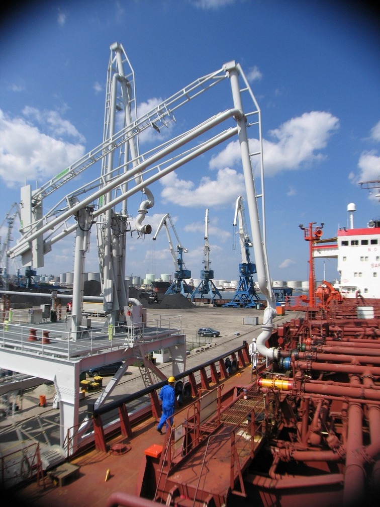
One of the fundamental parameters used to define a marine loading arm is its operating envelope, or working envelope. This is the three-dimensional volume within which the vessel manifold can move while the loading arm remains connected and operates safely
To define the operating envelope, the following parameters should be considered, among others: vessel types and dimensions; vessel deadweight tonnage (DWT); height and location of vessel manifolds; variation in draft between loaded and unloaded conditions; tidal range; expected vessel movements during transfer; jetty elevation above water level; distance between the jetty face and the vessel manifold; environmental design conditions applicable to the loading arm.
For this reason, a marine loading arm should not be specified solely on the basis of its diameter and length. The vessel, jetty geometry and operating conditions must be evaluated together.
If, during a transfer operation, the vessel approaches the limits of the safe operating envelope, the system can activate warning alarms. On installations equipped with an emergency release system, if the vessel continues to move beyond the allowable limits, the system can stop product flow and perform a controlled emergency separation of the loading arm from the vessel.
There is no universal number of loading arms required for a marine terminal. The number of marine loading arms is not determined simply by vessel size. A basic installation may operate with a single arm, while another terminal may use several loading arms simultaneously.
The number of arms required depends primarily on: the number of products to be transferred; required total flow rate; selected line diameter; whether a vapor return line is required; whether different products must be transferred simultaneously; the maximum allowable vessel loading or unloading time; the terminal’s operating and redundancy philosophy.
High-capacity terminals frequently install several loading arms in parallel to achieve high transfer rates or to handle different product and vapor lines simultaneously.
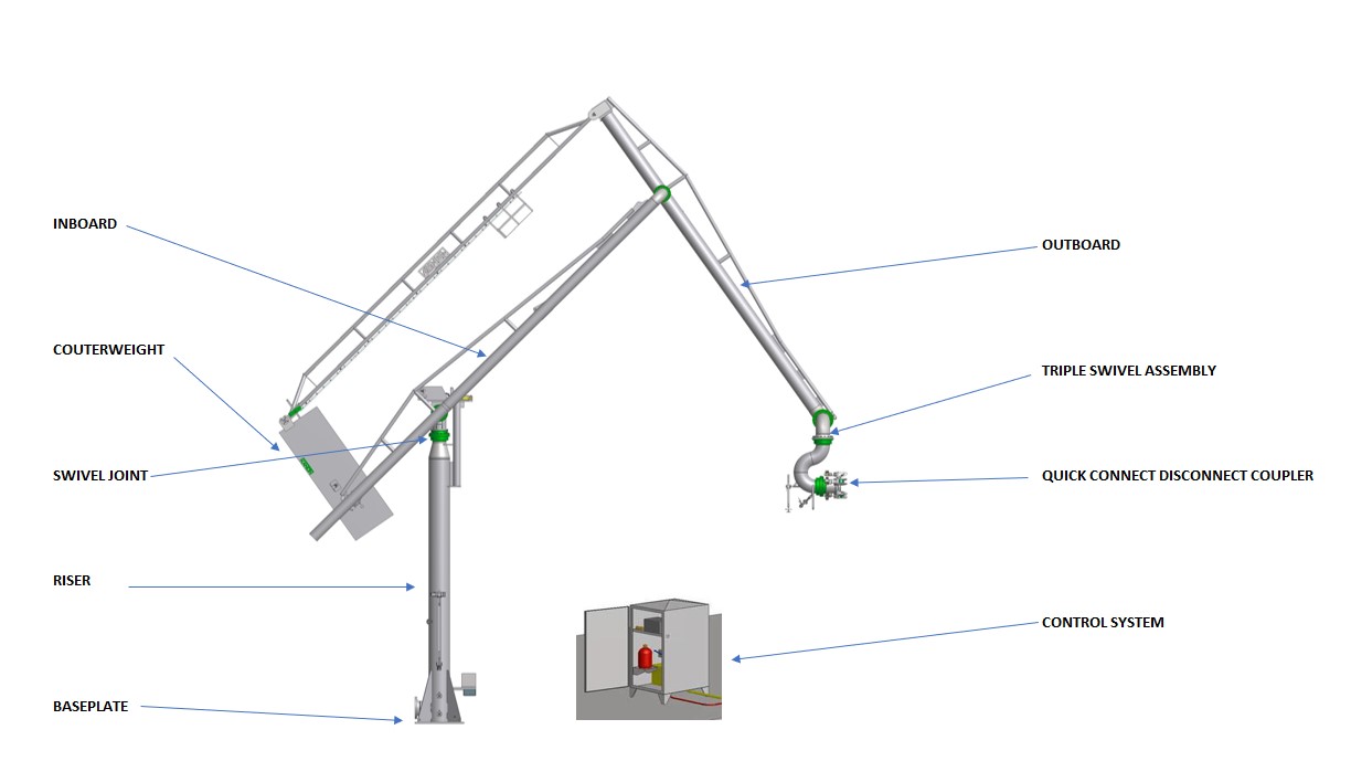
A marine loading arm incorporates high-precision mechanical, hydraulic and safety subsystems:
Marine loading arms for LNG (Liquefied Natural Gas) operate under conditions that differ significantly from those associated with liquid hydrocarbons handled at ambient temperature. LNG is transferred at approximately −162°C (−260°F), requiring all components to be specifically designed for cryogenic service.
A fundamental difference lies in the loading arm structure. The LNG product piping is not intended to act as the primary load-bearing structure for the external loads considered in the project. Instead, the LNG piping is integrated into a dedicated supporting structure, avoiding unnecessary structural stresses on the line carrying the cryogenic fluid.
Specific designs are also used to prevent moisture ingress and the resulting ice formation around the articulations. Equipment installed at the end of the arm, including the QC/DC and ERC, must be specifically suitable for LNG service and must maintain functionality and tightness at cryogenic temperatures.
LNG terminals commonly use separate loading arms for the liquid phase and vapor return.
A marine loading arm forms part of a broader ship-to-shore transfer system.
A marine terminal may also incorporate:
The definition and integration of these systems should form part of the terminal’s overall safety and operating philosophy.
Design criteria depend on the transferred product and the specific application.
Commonly referenced international standards and industry guidance include:
In addition, the design must comply with the applicable project requirements for pressure, temperature, materials, hazardous-area classification and safety.
For most industrial marine terminals, marine loading arms provide significant advantages over flexible hoses.
For an initial selection, the following information should be defined at a minimum:
Based on this information, the initial loading arm geometry can be determined and its operating envelope checked against the different vessels expected to call at the terminal. For a new project or the replacement of existing marine loading arms, you may complete our Marine Loading Arm Design Data Sheet or contact us for an initial technical review of the application.
Marine loading arms are one of the key components of the interface between a vessel and a storage or process terminal.
Proper selection requires evaluating multiple parameters and taking into account the expected movements of the vessel. A properly specified loading arm enables efficient, continuous and safe transfer operations at the ship-to-shore interface.
For questions regarding a new installation or the modernization of an existing terminal, you may contact us or complete our technical form so that we can review the technical requirements of your project.
 EN
EN  ES
ES  FR
FR